NetApp introduced C190 for Small Business, following the new platform A320 with ONTAP 9.6.
C190
This new All-Flash system has:
Fixed format, with no ability to connect additional disk shelves:
Only 960 SSD drives installed only in the controller chassis
Only 4 configs: with 8, 12, 18 or 24 drives
Effective capacity respectively: 13, 24, 40 or 55 TB
Supports ONTAP 9.6 GA and higher
C190 build with the same chassis as A220, so per HA pair you’ll get:
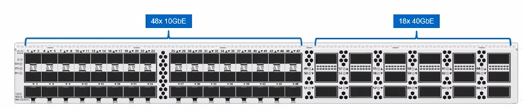
4x 10Gbps SFP cluster ports
8x UTA ports (10 Gbps or FC 16Gbps)
There is a model with 10GBASE-T ports instead of UTA & cluster interconnect ports (12 ports total). Obviously BASE-T ports do not support FCP protocol
There will be no more “useful capacity”, NetApp will provide only “Effective capacity”:
With dedup, compression, compaction and 24 x 960 GB drives the system provide ~50 TiB Effective capacity. 50 TiB is pretty reliable conservative number because it is even less than ~3:1 data reduction
Deduplication snapshot sharing functionality introduced in previous ONTAP versions allows gaining even better efficiency
And of course FabricPool tiering can help to save much space
C190 comes with Flash bundle which adds to Basic software:
SnapMirror/SnapVault for replication
SnapRestore for fast restoration from snapshots
SnapCenter for App integration with storage snapshots
FlexClone for thing cloning.
Fixed configuration with built-in drives, I personally think, is an excellent idea in general, taking into account we have such a wide variety of capacity in SSD drives nowadays and even more to come. Is this the future format for all storage systems with flash? Though C190 supports only 960 GB SSD drives, and new Mid-range A320 system, can have more than one disk shelf.
Also, in my opinion, C190 can more or less cover market place left after the announcement for the end of sale (EOS) of hardware and virtual AltaVault (AVA, and recently know under a new name “Cloud Backup”) appliances thanks to FabricPool tiering. Cloud Backup appliances still available through AWS & Azure market places. Especially now it is the case after FabricPool in ONTAP 9.6 no longer have a hard-coded ratio for how many data system can store in the cloud compare to hot tier & allows wright-through with “All” policy.
Turns out information about storage capacity “consumed” more comfortable in the form of effective capacity. All this useful capacity, garbage collector and other storage overheads, RAIDs and system reserves are too complicated, so hey, why not? I bet idea of showing only effective capacity influenced by vendors like Pure, which have very effective marketing for sure.
Cons
MetroCluster over IP is not supported in C190, while Entry-level A220 & FAS2750 systems support MCC-IP with ONTAP 9.6
C190 require ONTAP 9.6, and ONTAP 9.6 do not support 7MTT.
All product names, logos, and brands are the property of their respective owners. All company, product, and service names used in this website are for identification purposes only. No one is sponsoring this article.
ONTAP is considered as a unified storage system, meaning it supports both block (FC, FCoE, NVMeoF and iSCSI) & file (NFS, pNFS, CIFS/SMB) protocols for its clients. SDS versions of ONTAP (ONTAP Select & Cloud Volumes ONTAP) do not support FC, FCoE or FC-NVMe protocols because of their software-defined nature.
Physical ports, VLANs and ifgroups considered as “ports” in ONTAP. Each port can run multiple LIFs. If a port has at least one VLAN, then LIFs can be created only on VLANs, not anymore on the port itself. If a port part of an ifgroup, LIFs can be created only on top of the ifgroup, not on the port itself anymore. If a port part of ifgroup on top of which created one or a few VLANs, LIFs can be created only on top of those VLANs, not on ifgroup or physical port anymore. It is very common configuration when two ports are part of an ifgroup and a few VLANs created for protocols. Here are two very popular examples, in this examples storage system configured with:
SMB for PC users (MTU 1500)
Popular example: User home directories
SMB for Windows Servers (MTU 9000)
Use case: MS SQL & Hyper-V
NFS for VMware & Linux Servers (MTU 9000)
Use-case: VMware NFS Datastore
iSCSI for VMware, Linux & Windows Servers (MTU 9000)
Block-deice for OS boot and some other configs, like Oracle ASM
Example 1 is for customers who want to use all of the Ethernet-based protocols, but have only 2 ports per node. Example 2 is more preferable with dedicated Ethernet ports for iSCSI traffic if a storage node have sufficient number of ports.
Notice Example 1, has two iSCSI VLANs A & B, which are not necessary, I would use two, in order to increase number of connections over ifgrp to increase load-balancing but it is up to storage & network admins. Normally each, iSCSI-A & iSCSI-B would use a separate IP subnet. See ifgroup section for the network load-balancing explanation.
VLANs
VLANs in ONTAP allow to separate two IP networks one from another and often used with NFS, CIFS and iSCSI protocols, though multiple IP addresses allowed on a single port or VLAN. A VLAN can be added on a physical Ethernet port or to an ifgroup.
ifgroup
Interface group is a collection of a few ports (typically with the same speed). Ports from a single ifgroup must be located on a single node. An ifgroup provide network redundancy to ethernet. Each ifgroup perceived and used as a physical port. One of the most notable & used type of ifgroup is Dynamic multimode. Dynamic multimode enables LACP protocol on ports so in case one port in a group dies another will be used fully transparently to upper-level protocols like NFS, SMB and iSCSI. Most notable in LACP is the ability to distribute data across links in attempt to equally load all the links in the ifgroup.
Ports starting with latter “e“, means it is a physical port, then number of PCIe bus (0 means on-board ports), and then another latter starting with “a” which represents index of the port on the PCIe bus. While ifgroup (virtual aggregated) port names starts with “a” (can be any latter), then number, and then another latter, for example a1a, to keep same format as physical ports for naming convention, even though number and the ending latter no longer represents anything in particular (i.e. PCIe bus or port position on the bus), but used only as index to distinguish from other ports.
Unfortunately LACP load distribution is far from perfect: the more hosts in network communicate with an ifgroup, the more probability to equally distribute traffic across network ports. LACP uses a single static formula depending on source and destination information of a network packet, there is no intellectual analysis and decision-making as for example in SAN protocols and there is no feedback from lower Ethernet level to upper-level protocols. Also LACP often used in conjunction of Multi-Chassis Ether Channel (vPC is another commercial name) functionality, to distribute links across a few switches and provide switch redundancy, which require some additional efforts from switch configuration and the switches themselves. While on another hand SAN protocols do not need switches to provide this type of redundancy because it done on protocol upper level. This is the primary reason why SMB and NFS protocols developed their extensions to provide similar functionality: to more intellectually and equally distribute load across links and be aware of network path status.
One day these protocols will fully remove necessity for Ethernet LACP & Multi-Chassis Ether Channel: pNFS, NFS Session Trunking (NFS Multipathing), SMB Multichannel and SMB Continuous Availability. Until then we going to use ifgroups with configurations which do not support those protocols.
NFS
NFS was the first protocol available in ONTAP. The latest versions of ONTAP 9 support NFSv2, NFSv3, NFSv4 (4.0 and 4.1) and pNFS. Starting with 9.5, ONTAP support 4-byte UTF-8 sequences in names for files and directories. Network switch technically is not required for NFS traffic and direct host connection is possible, but network switch is used in all the configurations to provide additional level of network redundancy and be able easier add new hosts when needed.
SMB
ONTAP supports SMB 2.0 and higher up to SMB 3.1. Starting with ONTAP 9.4 SMB Multichannel, which provides functionality similar to multipathing in SAN protocols, is supported. Starting with ONTAP 8.2 SMB protocol supports Continuous Availability (CA) with SMB 3.0 for Microsoft Hyper-V and SQL Server. SMB is a session-based protocol and by default does not tolerate session brakes, so SMB CA helps to tolerate unexpected session loss, for example in case a network port went down. ONTAP supports SMB encryption, which is also known as sealing. Sped up AES instructions (Intel AES NI) encryption is supported in SMB 3.0 and later. Starting with ONTAP 9.6 FlexGroup volume supports SMB CA and thus support MS SQL & Hyper-V on FlexGroup. Network switch technically is not required for SMB traffic and direct host connection is possible, but network switch is used in all the configurations to provide additional level of network redundancy and be able easier add new hosts when needed. Here is the hierarchy visualization & logical representation of NAS protocols in ONTAP cluster and corresponding commands (highlighted in grey):
Each NAS LIF can accept NFS & SMB traffic, but usually engineers tend to separate them on separate LIFs.
FCP
ONTAP on physical appliances supports SCSI-based FCoE as well as FC protocols, depending on HBA port speed. Both FC & FCoE are known under a single umbrella name FCP. An iGroup is a collection of WWPN address from initiator hosts which allowed to access storage LUNs. WWPN address is interface on FC or FCoE port. typically you need to add all the initiator host ports to iGroup to allow multipathing work properly. ONTAP uses N_Port ID Virtualization (NPIV) for FC data and therefore require a FC network switch (typically at least two) which also supports NPIV, direct FC connections from host to storage are not supported. Here is the hierarchy visualization & logical representation of FCP protocols in ONTAP cluster and corresponding commands (highlighted in grey):
iSCSI is another SCSI-based protocol encapsulated in IP/Ethernet transport. NetApp also supports Data Center Bridging (DCB) protocol for some models, depending on Ethernet port chips. Network switch technically is not required and direct host connection is possible, but network switch is recommended to be able easier add new hosts when needed. Network switch technically is not required for iSCSI traffic and direct host connection is possible if number of storage ports allows, though network switch can be used to easier add new hosts when needed. Network switch is recommended to have with iSCSI. Here is the hierarchy visualization & logical representation of iSCSI protocol in ONTAP cluster and corresponding commands (highlighted in grey):
NVMeoF
NVMe over Fabrics (NVMeoF) refers to the ability to use NVMe protocol over existing network infrastructure like Ethernet (Converged or traditional), TCP, Fiber Channel or InfiniBand for transport (as opposite to run NVMe over PCIe without additional encapsulation). NVMe is SAN block data protocol. In contrast to NVMe (just) where an extra layer of transport is not used and devices connected directly to PCIe bus.
Starting with ONTAP 9.5, NVMe ANA protocol supported which provide, similarly to ALUA, multipathing functionality to NVMe. ANA for NVMe currently supported only with SUSE Enterprise Linux 15, VMware 6.7 and Windows Server 2012/2016. FC-NVMe without ANA supported with SUSE Enterprise Linux 12 SP3 and RedHat Enterprise Linux 7.6.
FC-NVMe
NVMeoF supported only on All-Flash FAS systems and not for Entry level A200 and A220 systems due to the lack of FC 32 Gb ports. Subsystem in NVMe used for the same purpose as iGroups, it allows initiator host NQN addresses which allowed to access a namespace. A namespace in this context is very similar to a LUN in FCP or iSCSI. Do not mix up namespace term in NVMe with a single namespace in ONTAP cluster. Here is the hierarchy visualization & logical representation of FC-NVMe protocol in ONTAP cluster and corresponding commands (highlighted in grey):
Spirit of this article
This article explains principles, architecture, NetApp’s unique approaches and maybe even spirit of ONTAP clusterization. Each configuration, model and appliance have their nuances, which left out of the scope of this article. I’ve tried to give a general direction of the ideas behind NetApp innovative technologies, while (trying) not putting too many details to the equation to keep it simpler but not to lose important system architecture details. This is a far not complete story about ONTAP; for example, I didn’t mention about 7-Mode Transition Tool (7MTT) required for the transition to Clustered ONTAP to make complex information easier to consume nor didn’t go to WAFL detail explanation. Therefore some things might be a bit different in your case.
Summary
Clustered ONTAP first time was introduced around 2010 in version 8. After almost 10 years of hardening ONTAP (cluster) become mature, highly scalable and flexible solution with not just unique, unprecedented on the market functionalities in a single product but also impressive performance thanks to its WAFL versatility & clusterization capabilities.
Please note in this article I described my own understanding of the internal organization of ONTAP systems. Therefore, this information might be either outdated, or I simply might be wrong in some aspects and details. I will greatly appreciate any of your contribution to make this article better, please leave any of your ideas and suggestions about this topic in the comments below.
All product names, logos, and brands are property of their respective owners. All company, product and service names used in this website are for identification purposes only.
Horizontal scaling ONTAP clusterization came from Spinnaker acquisitions and often referred by NetApp as “Single Namespace,” “Horizontal Scaling Cluster,” or “ONTAP Storage System Cluster,” or “Scale-out cluster,” or just “ONTAP Cluster.” This type of clusterization often confused with HA pair or even with MetroCluster functionality. So to distinguish this one from others in ONTAP I will call it as the third type of clusterization. While MetroCluster and HA are Data Availability and even Data Protection technologies, single namespace clusterization does not provide data protection nor Data Availability: if there will be a hardware failure, the third type of clusterization is not involved in helping to mitigate such a problem. ONTAP forms (third type of) cluster out of one or a few HA pairs (multiple single-nodes are not supported in a single cluster) and adds to ONTAP system Non-Disruptive Operations (NDO) functionality such as non-disruptive online data migration across nodes in the cluster and non-disruptive hardware upgrade or online IP address migration. Data migration for NDO operations in ONTAP Cluster require dedicated Ethernet ports for such operations; they called cluster interconnect interfaces and does not use HA interconnect interfaces for this purpose. Cluster interconnect and HA interconnect interfaces couldn’t share the same ports, until A320 system.
Cluster interconnect with a single HA pair could have directly connected cluster interconnect ports (switch-less config) while systems with 4 or more nodes require two dedicated Ethernet cluster interconnect switches. ONTAP Cluster could consist only from an even number of nodes (they must be configured as HA pairs) except for Single-node cluster. Single-node cluster ONTAP system also called non-HA (or stand-alone), in such a configuration another cluster nodes cannot be added to a single node cluster, but single-node cluster can be converted to HA system and then other HA pairs can be added. ONTAP Cluster managed with a single pane of glass built-in management through Web-based GUI, CLI (SSH and PowerShell) and API. ONTAP Cluster provides Single Namespace for NDO operations through Storage Virtual Machines (SVM). Single Namespace in ONTAP system is a name for a collection of techniques used by (the third type) cluster to provide a level of abstraction and separate data from front-end network connectivity with data protocols like FC, FCoE, FC-NVMe, iSCSI, NFS and SMB from the data in volumes and therefore provide data virtualization. This virtualization provides online data mobility across cluster nodes while clients connected over data protocols still can access their data.
The general idea behind the single namespace is to trick clients so they would think they connected to a single device, while in reality connected to a cluster which consists of a bunch of nodes. This ”trick” work in different ways with different protocols. For example with FC protocol each node’s FC port gets unique WWPN address, while cluster SVM has a single WWNN, in this way client connected to the cluster consider it as a single FC node with multiple active ports, while some of them reported as optimized for traffic and some are none-optimized, in a very similar way it works with iSCSI and NVMeoF. With FC & iSCSI ALUA protocol used to switch between ports & links in case it becomes unavailable. With pNFS cluster operate in a similar to SAN protocol way: nodes in a cluster have interfaces with IP address, so clients perceive SVM as a single node with multiple active interfaces. ONTAP reports to clients ports as optimized which have direct access to nodes which serve volume with the data, and only if those ports not available, clients will use other active none-optimized ports. If protocols like NFS v3, NFS v4, SMB v2, and SMB v3 do not have such capabilities like SAN ALUA or pNFS, then ONTAP has another trick in its sleeve: Single Namespace provides several techniques for non-disruptive IP address migration for data protocols in case node or port dies.
SMB Continuous Availability (CA) extension to SMB v3 allows clients not to drop connections and this provides transparent failover in case a port, link or a node went down. Therefore MS SQL & Hyper-V servers on file share can survive. Without CA support in SMB protocol, in case of IP address migration to another port, clients will get session disruption, so only user file shares recommended to use. Since NFS v3 is a stateless protocol, if an IP address will migrate to another port or node, clients will not experience interruption. In the case of SAN, protocols interfaces do not migrate, but rather a new path selected.
Network access: Indirect data path
In some cases when data resides on one controller and this data accessed through another controller, then indirect data access occurs: For example hosts access network address through LIF 3A on node 3, while volume with data located on data_aggregate01 on node 1. In this scenario node 3 will access controller 1 through cluster interconnect interfaces & switches, get the data from node 1, and provide the information to the hosts requested it from LIF 3A interface which located on node 3 ports, and in some cases controller which owns data, in this example node 1, can reply directly to hosts. This functionality introduced as part of single namespace strategy (the third type of clusterization) to always provide hosts access to data no matter of location of the network addresses and volumes. Indirect data access occurs rarely in the cluster in situations like a LIF migrated by admin or cluster to another port; a volume migrated to another node; or if a node port went down. Though indirect data path adds some small latency to operations, in most of the cases it can be ignored. Some protocols like pNFS, SAN ALUA, NVMe ANA can automatically detect and switch its primary path to ports on the node with direct access to the data. Again, this (third) type of clusterization is not a data protection mechanism, but rather online data migration functionality.
Heterogeneous cluster
Cluster (the third type of clusterization) can consist of different HA pairs: AFF and FAS, different models and generations, performance and disks, and can include up to 24 nodes with NAS protocols or 12 nodes with SAN protocols. SDS systems can’t intermix with physical AFF or FAS appliances. The main purpose of the third type of customization is not data protection but rather non-disruptive operations like online volume migration or IP address migration between all the nodes in the cluster.
Storage Virtual Machine
Also known as Vserver or sometimes SVM. Storage Virtual Machine (SVM) is a layer of abstraction, and alongside with other functions, it virtualizes and separates physical front-end data network from data located on FlexVol volumes. Used for Non-Disruptive Operations and Multi-Tenancy. SVMs lives on nodes and on the image below pictured on disk shelves around volummes just to demonstrate each volume belong only to a single SVM.
Multi-Tenancy
ONTAP provides two techniques for Multi-Tenancy functionality: SVM and IP Spaces. On the one hand, SVMs are like KVM Virtual Machines; they provide virtualization abstraction from physical storage but on another hand quite different because unlike ordinary virtual machines does not allow to run third-party binary code like in Pure storage systems; they just provide a virtualized environment and storage resources instead. Also, SVMs, unlike ordinary virtual machines, does not run on a single node, SVM runs as a single entity on the whole cluster (unless it looks to system admin that way). SVM divide storage system into slices so few divisions or even organizations can share a storage system without knowing and interfering with each other while using same ports, data aggregates and nodes in the cluster and using separate FlexVol volumes and LUNs. Each SVM can run its own front end data protocols, a set of users, use its network addresses and management IP. With the use of IP Spaces users can have the same IP addresses and networks on the same storage system without interfering and network conflicts. Each ONTAP system must run at least one Data SVM to function but may run more. There are a few levels of ONTAP management: Cluster Admin level has all the privileges. Each Data SVM provides to its owner vsadmin user which have nearly full functionality like Cluster Admin level but lucks management of physical level like RAID group configuration, Aggregate configuration, physical network port configuration. Vsadmin can manage logical objects inside its SVM: create, delete and configure LUNs, FlexVol volumes and network interfaces/addresses so two SVMs in a cluster can’t interfere with each other. One SVM cannot create, delete, change or even see objects of another SVM so for SVM owners such an environment looks like they are only users on the entire storage system cluster. Multi-Tenancy is a free functionality in ONTAP. On the image below SVMs pictured on top of ONTAP cluster, but in reality, SVMs are part of ONTAP OS.
Non Disruptive Operations
There a few Non-Disruptive Operations (NDO) and Non-Disruptive Upgrade (NDU) with (Clustered) ONTAP system. NDO data operations include: data aggregate relocation within an HA pair between nodes, FlexVol volume online migration (known as Volume Move operation) across aggregates and nodes within the Cluster, LUN migration (known as LUN Move operation) between FlexVol volumes within the Cluster. LUN move and Volume Move operations use Cluster Interconnect interfaces for data transfer (HA-CI is not in use for such operations). SVM behave differently with network NDO operations, depending on the front-end data protocol. To decrease latency to its original level FlexVol volumes and LUNs should be located on the same node with network address through which the clients access the data, so network address could be created for SAN or moved for NAS protocols. NDO operations are free functionality.
NAS LIF
For NAS front-end data protocols there are NFSv2, NFSv3, NFSv4, CIFSv1, SMBv2, and SMB v3 protocols which do not provide network redundancy with the protocol itself, so they rely on storage and switch functionalities for this matter. ONTAP support Ethernet Port Channel and LACP with its Ethernet network ports on L2 layer (known in ONTAP as interface group or ifgrp), within a single node. And also ONTAP provides non-disruptive network failover between nodes in the cluster on L3 layer with migrating Logical Interfaces (LIFs) and associated IP addresses, similarly to VRRP, to the survived node and back home when failed node restored.
Though new versions of NAS protocols have built-in multipathing functionality: Extensions to NFS v4.1 protocol like pNFS (Supported starting with ONTAP 9.0) and NFS Session Trunking (NFS Multipathing. Not yet supported with ONTAP 9.6), and SMB v3 extension called SMB Multichannel (Available starting with ONTAP 9.4) allows automatically switch between paths in case of network link failure, while SMB Continuous Availability (CA) helps to preserve sessions without interruption. Unfortunately, all of these capabilities have limited support from clients. Until they become more popular ONTAP, will relay on build-in NAS LIF migration capabilities to move interfaces with assigned network addresses to survived node & port.
FailoverGroup
Failover group is functionality available only to NAS protocols and applied only to Ethernet ports/VLANs. SAN interfaces cannot (and do not need) to online migrate across cluster ports like NAS LIFs, therefore do not have failover group functionality. Failover group is a prescription to a LIF interface were to migrate in case if the hosted port will go down and should it return back automatically. By default FailoverGroup equal to Broadcast Domain. It is a good practice to specify manually between which ports a LIF can migrate, especially in the case where a few VLANs are used, so the LIF would not migrate to another VLAN. A failover group can be assigned to multiple LIFs, and each LIF can be assigned to a single failover group.
Broadcast Domain
A Broadcast Domain is a list of all the ethernet ports in the cluster which using the same MTU size and therefore used only for Ethernet ports. In many cases, it is a good idea to separate ports of different speeds. Unless of cause storage administrator wants to mix ports with lower speed & higher speed with the conjunction of a failover group to prescribe LIF migration from high-speed ports to slower speed ports in case if the first ports are unavailable, that is rarely the case and usually needed only with systems with a minimal number of ports. Each Ethernet port can be assigned only to one Broadcast Domain. If a port is a part of ifgroup, then such ifgroup port assigned to a Broadcast Domain. If a port or an ifgroup have VLANs, then Broadcast Domain assigned to each VLAN on that port or ifgroup.
SAN LIF
For front-end data SAN protocols. ALUA feature used for network load balancing and redundancy with FCP and iSCSI protocols, so all the ports on the node where data located are reported to clients as an active optimized (preferred), and if there are more than one port, ALUA will make sure hosts will load balance between them. And similarly it works with ANA in NVMe. While all other network ports on all other nodes in the cluster are reported by ONTAP to hosts as active none-optimized, so in case of one port or entire node goes down, the client will have access to its data using non-optimized path. Starting with ONTAP 8.3 Selective LUN Mapping (SLM) was introduced to reduce the number of unnecessary paths to the LUN and removes non-optimized paths to the LUN through all other cluster nodes except for HA partner of the node owning the LUN so cluster will report to the host paths only from the HA pair where LUN is located. Because ONTAP provides ALUA/ANA functionality for SAN protocols, SAN network LIFs do not migrate like with NAS protocols. When volume or LUN migration is finished, it is transparent to the storage system’s clients because of ONTAP Architecture and can cause temporary or permanent data indirect access through ONTAP Cluster interconnect (HA-CI is not in use for such situations) which will slightly increase latency for the clients. SAN LIFs used for FC, FCoE, iSCSI & FC-NVMe protocols.
iSCSI LIFs can live on the same ifgroup, port or VLAN with NAS LIFs since both using Ethernet ports.
On the image below pictured ONTAP cluster with 4 nodes (2 HA pairs) and a host accessing data over a SAN protocol.
VIP (Virtual IP) LIFs, also known as BGP LIFs, require Top-of-the-Rack BGP Router to be used. VIP data LIFs used with ethernet for NAS environment. VIP LIFs, automatically load-balance traffic based on routing metrics and avoids inactive unused links and ports, unlike it usually happens with NAS protocols. VIP LIFs provides distribution across all the LIFs in the cluster, not limited to a single node as in NAS LIFs. VIP LIFs provides smarter load balance than it was realized with hash algorithms in Ethernet Port Channel & LACP with interface groups. VIP LIF interfaces are tested and can be used with MCC and SVM-DR and provide a more reliable, predictable and faster switch to the survived links & paths than NAS LIFs but require BGP routers.
Management interfaces
Node management LIF interface can migrate with associated IP address across Ethernet ports of a single node and available only while ONTAP running on the node. Usually, management interface placed on e0M port of the node; Node management IP sometimes used by cluster admin to communicate with a node to cluster shell in rare cases where commands have to be issued from a particular node. Cluster Management LIF interface with associated IP address available only while the entire cluster is up & running and by default can migrate across Ethernet ports, often located on one of the e0M ports on one of the cluster nodes and used by the cluster administrator for storage management. Management interfaces used for API communications, HTML GUI & SSH console management, by default SSH, connect administrator with cluster shell. Service Processor (SP) or BMC interfaces available only at hardware appliances like FAS & AFF, and each system has only SP or BMC. SP/BMC allows SSH out-of-band console communications with an embedded small computer installed on controller main-board and similarly to IPMI, or IP KVM enables to connect, monitor & manage controller even if it does not boot ONTAP OS. With SP/BMC it is possible to forcibly reboot or halt a controller and monitor coolers, temperature, etc.; once connected to SP/BMC console by SSH administrator can switch to cluster shell through it with issuing system console command; each controller has one SP/BMC interface which does not migrate like some other management interfaces. Usually, e0M and SP both lives on single management (wrench) physical Ethernet port but each have its own dedicated MAC address. Node LIFs, Cluster LIF & SP/BMC often using the same IP subnet. SVM management LIF, similarly to cluster management LIF, it can migrate across all the Ethernet ports on the nodes of the cluster and dedicated for a single SVM management. SVM LIF does not have GUI capability and can facilitate only for API Communications & SSH console management; SVM management LIF can live on e0M port but often placed by administrators on a data port in the cluster and usually on a dedicated management VLAN and can be different from IP subnets of node & cluster LIFs.
Cluster interfaces
Each cluster interconnect LIF interface usually lives on dedicated Ethernet port and cannot share ports with management and data interfaces. Cluster interconnect interfaces used for horizontal scaling functionality at times when, for example, a LUN or a Volume migrates from one node of the cluster to another node; cluster interconnect LIF similarly to node management LIFs can migrate only between ports of a single node. A few cluster interconnect interfaces can coexist on a single port, but usually, this happens temporarily because of cluster port recabling. Inter-cluster interface LIFs on another hand can live and share the same Ethernet ports with data LIFs and used for SnapMirror replication; Inter-cluster interface LIFs, similarly to node management & cluster interconnect LIFs can only migrate between ports of a single node.
Please note in this article I described my own understanding of the internal organization of ONTAP systems. Therefore, this information might be either outdated, or I simply might be wrong in some aspects and details. I will greatly appreciate any of your contribution to make this article better, please leave any of your ideas and suggestions about this topic in the comments below.
All product names, logos, and brands are property of their respective owners. All company, product and service names used in this website are for identification purposes only.
I will call HA the first type of clusterization and its main purpose is data availability. Even though a single HA pair consists of two nodes (or controllers), NetApp has designed it in such a way it appears as a single storage system from clients perspective of view. HA configurations in ONTAP use several techniques to present the two nodes of the pair as a single system. This allows the storage system to provide its clients with nearly uninterrupted access to their data should a node fail unexpectedly.
For example: on the network level, ONTAP will temporarily migrate the IP address of the failed node to the surviving node, and where applicable it will also temporarily switch ownership of disk drives from the downed node to the surviving node. On the data level, the contents of the disks that are assigned to the downed node will automatically be available for use via the surviving node.
An aggregate can include only disks owned by a single node; therefore, each aggregate owned by a node and an upper objects such as FlexVol volumes, LUNs, File Shares served within a single controller (until FlexGroup). Since each node in HA pair can have its own disks and aggregates and serve them independently; therefore, such configurations are called Active/Active where both nodes are utilized simultaneously even though they are not serving the same data. In case one node fails, another will take over and serve its partner’s and its own disks, aggregates, and FlexVol volumes. HA configurations were only one controller has data aggregates, called Active/Passive, were passive node has only root aggregate and simply waiting to take over in case active will fail.
Once the downed node of the HA pair has been booted, up and running, a “giveback” command issued by defaul, to return disks, aggregates and FlexVol resources back to the original node.
Symmetric network access often goes together with Monolithic architectures but not always
Share-nothing architecture
There are storage systems where each node serves the same data with symmetrical network access and have monolithic storage architecture; ONTAP is not one of them. ONTAP using architecture known as share-nothing, meaning no special equipment really needed for such architecture and storage components are not used simultaneously by storage nodes: only one node serves each disk (also see the definition of what a disk drive in ONTAP is, and about exception with ADP drive partitioning), aggregate, FlexVol, LUN, and NVMe namespace at a time, and if that node fails, another takes over. Even though in hardware appliances based on ONTAP we can see ”special” devices like NVRAM/NVDIMM, and disks with dual ports, each node in an HA pair runs its own instance of ONTAP on two separate controllers were only NVLogs replicated over HA-CI connections between HA partners, though NVLogs are not used until an HA partner fails. Though ONTAP is using these special devices in its hardware appliances, SDS version of ONTAP can work without them and dual-port disks perfectly well: NVLogs are still replicated between HA partners, and instead of having two data ports and access the same disk drives with both controllers, ONTAP SDS can simply replicate data and keep two copies of data, like in MCC configurations. Share nothing architectures are particularly useful in scale-out clusters: you can add controllers with different models, configurations, disks, and even with slightly different versions of OS if needed.
On the contrary, storage systems with symmetrical network access often build on monolithic architectures, which in turn suitable only to SAN protocols. Note NetApp ASA systems build on ONTAP are not monolithic but still, provide symmetrical network access. While monolithic architecture might sound ”cool” and seem to give more performance from the first sight, on practice share nothing architectures shows no less performance. Also, the monolithic architectures have plenty of inflexibility and disadvantages. For example, when the industry moved to flash media turns out disks are no longer a performance bottleneck, but controllers and CPUs are. This means you need to add more nodes to your storage system to increase performance. This problem can be solved with scale-out clusters but monolithic architectures particularly very bad on that front. Let me explain why.
First of all, if you have a monolithic architecture, each controller needs to have access to each disk, and when you are adding new controllers you need to rearrange disk shelves connections to facilitate that need, second, all the controllers in such a cluster have to be the same model with the same firmware, these clusters become very hard to maintain and add new nodes, plus such architectures usually very limited with maximum number of controllers you can add to such a cluster. Another example, closer to practice then to theory: imagine after a 3 years you need to add new node to your cluster to increase performance, while on the market there most probably available more powerful controllers with the same price you’ve bought your old controllers, but you can add only old controllers to the cluster.
Due to its monolithic nature, it becomes a very complex architecture to scale, most vendors of cause trying to hide this underlying complexity from its customers to simplify the usage of such systems, and some A-Brand systems are excellent on that front. But still, monolithic inflexibility makes such systems complex on low-level and turns to be very expensive, because it requires specially designed hardware, mainboards, and special buses. While on another hand, share-nothing architectures need no modifications for commodity servers to be used as storage controllers and hardware storage appliances, while no scalability nor performance is the problem for them.
HA interconnect
High-availability clusters (HA clusters) is the first type of clusterization introduced in ONTAP systems (that’s why I call it the first). The first, the second and the third type of ONTAP clusterization are not official or well-known industry terms, – I’m using them only to differentiate ONTAP capabilities while keeping them under the same umbrella because on some level they all are clusterization technologies. HA aimed to ensure an agreed level of operations. People often confuse HA with the horizontal scaling ONTAP clusterization that came from the Spinnaker acquisition; therefore, NetApp, in its documentation for Clustered ONTAP systems, refers to an HA configuration as an HA pair rather than as an HA cluster. I will reference to horizontal scaling ONTAP (Spinnaker) clusterization as the third type of clusterization to make it even more difficult. I am just kidding, with doing so I’m drawing parallels with all three types of customization so you will easily find differences between them.
An HA pair uses network connectivity between the pairs called a High Availability interconnect (HA-IC). The HA interconnect can use Ethernet ( in some older systems you might find InfiniBand) as the communication medium. The HA interconnect used for non-volatile memory log (NVLogs) replication between two nodes in an HA pair configuration using RDMA technology to ensure an agreed level of operations during events like unexpected reboots. Usually, ONTAP assigns dedicated, non-sharable HA ports for HA interconnect which could be external or built-in to storage chassis (and not visible from the outside). We should not confuse the HA-IC with the inter-cluster or intra-cluster interconnects that are used for SnapMirror. Inter-cluster and intra-cluster interfaces can coexist with interfaces used for data protocols on data ports. Also, HA-CI traffic should not be confused with Cluster Interconnect traffic used for horizontal scaling & online data migration across the multi-node cluster, and usually these two interfaces live on two different ports. HA-IC interfaces are visible only on the node shell level. Starting with A320 HA-IC and Cluster interconnect traffic to use the same ports.
MetroCluster
MetroCluster is a free functionality for ONTAP systems for metro high availability with synchronous replication between two sites; this configuration might require some additional equipment. There can be only two sites. To distinguish between “old” MetroCluster in 7-Mode and “new” MetroCluster in Cluster-Mode, last one shortened as MCC. I will call MCC as the second type of ONTAP clusterization. The primary purpose of MCC clusterization is to provide data protection and data availability across two geographical locations and switch clients from one site to another in case of a disaster to continue access to the data.
MetroCluster (MCC) is an additional level of data availability to HA configurations and supported initially only with FAS and AFF storage systems, later SDS version of MetroCluster was introduced with ONTAP Select & Cloud Volumes ONTAP products. An MCC configuration consists of two sites (each site can have a single node or HA pair), both form MetroCluster. The distance between sites can reach up to 300 km (186 miles) or even 700 km (436 miles), therefore, called geo-distributed system. Plex and SyncMirror are the critical underlying technologies for MetroCluster which synchronize data between two sites. In MCC configurations NVLogs are also replicated among storage systems between sites in this article I will refer this traffic as metrocluster traffic, to distinguish it from HA interconnect, and Cluster interconnect traffic.
MetroCluster uses RAID SyncMirror (RSM) and plex technique where on one site number of disks form one or more RAID groups aggregated in a plex, while the second site have the same amount of disks with the same type and RAID configuration aggregated into the second plex where one plex replicate data to another. Alongside with NVLogs ONTAP replicates Configuration Replication Service (CRS) metadata. NVLogs are replicated from one system to another as part of SyncMirror process and then on destination system NVLogs restored to MBUF and dumped to disks as part of next CP process, while from the logical perspective of view it looks like data synchronously replicated between two plexes groups. To simplify things, NetApp usually shows that one plex synchronously replicates to another, but in reality, NVLogs synchronously replicated between non-volatile memories of two sites. Two plexes form an aggregate and in case of a disaster on one site, the second site provides read-write access to the data. MetroCluster Support FlexArray technology and ONTAP SDS.
As part of the third type of clusterization, individual data volumes, LUNs and LIFs could online migrate across storage nodes in the MetroCuster only within a single site where data originated from: it is not possible to migrate individual volumes, LUNs or LIFs using cluster capabilities across sites unless MetroCluster switchover operation (the second type of clusterization) is used to switch entire half of the cluster with all the data, volumes, LIFs and storage configuration from one, so clients and applications access to all the data from another location.
With MCC it is possible to have one or more storage nodes per site, so one node per site known as 2-node configuration (or two-pack configuration), 2-node per site known as 4-node configuration and 8-node configuration with 4-nodes per site. Local HA partner (if exists) and remote partner must be the same model: in 2 or 4-node configurations, all nodes must be the same model & configuration. In MCC configuration each one remote and one local storage node form a Disaster Recovery Pare (DR Pare) across two sites while two local nodes (if there is partner) form local HA pair, thus each node synchronously replicates data in non-volatile memory two nodes: one remote and one local (if there is one). In other words, the 4-node configuration consists of two HA pares and in this case NVLogs replicated to a remote site and local HA partner as in normal non-MCC HA system, while 2-node configuration NVLogs replicated only to its remote partner.
MCC with one node on each site called two-pack (or 2-node) MCC configuration.
8-Node MCC
8-node MCC configuration consists of two almost independent 4-node MCC (each 4-node with two HA pair), as in 4-node configuration, each storage node have only one remote partner and only one local HA partner. The only difference between two completely independent 4-node MCC and 8-node configuration MetroCluster is that 8-node share cluster interconnect switches therefore entire 8-node cluster seen by clients as a single namespace system administrator can move data online between all the nodes in MetroCluster within a local site. Example of 8-node MCC is four nodes of AFF A700 and four nodes of FAS8200, where two nodes of A700 and two nodes of FAS8200 on one site and the second half on the another site.
MCC network transport: FC & IP
MCC can use two network transports for synchronization: FC or IP. Most FC configurations require dedicated FC-VI ports usually located on an FC-VI card but some FAS/AFF models can convert on-board FC ports to FC-VI mode. IP requires iWRAP interfaces which can live on ethernet ports (25 GbE or higher), which usually available on an iWRAP card. Some models like Entry-level A220 can use onboard ports and share ports with cluster interconnect traffic, while MCC-FC do not support Entry systems.
MCC: Fabric & Stretched
Fabric configurations are configurations with switches, while stretched configurations are configs without a switch. Both Fabric & Stretched terms usually applies only to FC network transport because IP transport always require a switch. Stretched configs can use only 2-nodes in a MetroCluster. With MCC FC stretched configs it is possible to build 2-node cluster stretched up to 300 meters (984 feet) without a switch, such configurations require special optical cables with multiple fibers in it, because of necessity to cross-connect all controllers and all disk shelves. To reduce the number of fibers stretched configurations can use FC-SAS bridges used to connect disk shelves to it, then cross-connect controllers and the FC-SAS bridges and the second option to reduce the number of required fiber links is to use FlexArray technology instead of NetApp disk shelves.
Fabric MCC-FC
FAS and AFF systems with ONTAP software versions 9.2 and older utilize FC-VI ports and for long distances require dedicated only for MetroCuster four Fibre Channel switches (2 on each site) and 2 FC-SAS bridges per each disk shelf stack, thus minimum 4 total for 2 sites and minimum 2 dark fiber ISL links with optional DWDMs for long distances. Fabric MCC require FC-SAS bridges. 4-node and 8-node configurations require a pair of cluster interconnect switches.
MCC-IP
Starting with ONTAP 9.3 MetroCluster over IP (MCC-IP) was introduced with no need for a dedicated back-end Fibre Channel switches, no FC-SAS bridges and no dedicated dark fiber ISL which previously were needed for MCC-FC configurations. In such configuration disk shelves directly connected to controllers and cluster switches used for MetroCluster (iWRAP) and Cluster interconnect traffic. Initially, only A700 & FAS9000 systems supported MCC-IP. MCC-IP available only in 4-node configurations: 2-node Highly Available system on each site with two sites total. With ONTAP 9.4, MCC-IP supports A800 system and Advanced Drive Partitioning in the form of Rood-Data-Data (RD2) partitioning for AFF systems, also known as ADPv2. ADPv2 supported only on all-flash systems. MCC-IP configurations support single disk shelf per site where SSD drives partitioned in ADPv2. MetroCluster over IP requires Ethernet cluster switches with installed ISL SFP modules to connect with the remote location and utilize iWRAP cards in each storage controller for synchronous replication. Starting with ONTAP 9.5 MCC-IP supports distance up to 700 km and SVM-DR feature, AFF A300, and FAS8200 systems. Beginning with ONTAP 9.6 MCC-IP supports Entry-level systems A220 and FAS2750, also in these systems MCC (iWRAP), HA, and Cluster interconnect interfaces lives on the cluster interconnect onboard ports, while mid-range and high-end systems still require a dedicated iWRAP card.
Plex
Similar to RAID-1, plexes in ONTAP systems can keep mirrored data in two places, but while conventional RAID-1 must exist within the bounds of one storage system, two plexes could be distributed between two storage systems. Each aggregate consists of one or two plexes. Ordinary HA or single-node storage systems have only one plex for each aggregate while SyncMirror local or MetroCluster configurations have two plexes for each aggregate. Each plex includes underlying storage space from one or more NetApp RAID groups or LUNs from third-party storage systems (see FlexArray) in a single plex similarly to RAID-0. If an aggregate consists of two plexes, one plex is considered a master and the second as a slave; slaves must consist of the same RAID configuration and drives. For example, if we have an aggregate consisting of two plexes where the master plex consists out of 21 data and three parity 1.8 TB SAS 10k drives in RAID-TEC, then slave plex must consist of 21 data and 3 parity 1.8 TB SAS 10k drives in RAID-TEC. Second example with hybrid aggregates, if we have an aggregate consisted from two plexes where master plex consists of one RAID 17 data and 3 parity SAS drives 1.8 TB SAS 10k configured as RAID-TEC and second RAID in the master plex is RAID-DP with 2 data and 2 parity SSD 960 GB, then the second plex must have the same configuration: one RAID 17 data and 3 parity SAS 10k drives 1.8 TB configured as RAID-TEC and the second RAID in the slave plex in RAID-DP with 2 data and 2 parity SSD 960 GB. MetroCluster configurations use SyncMirror technology for synchronous data replication.
There are two SyncMirror options: MetroCluster and Local SyncMirror; both using the same plex technique for synchronous replication of data between two plexes. Local SyncMirror creates both plexes in a single controller and is often used for additional security to prevent failure for an entire disk shelf in a storage system. MetroCluster allows data to be replicated between two storage systems.
MetroCluster SDS
Is a feature of ONTAP Select software, similarly to MetroCluster on FAS/AFF systems MetroCluster SDS (MC SDS) allows to synchronously replicate data between two sites using Plex & SyncMirror and automatically switch to survived node transparently to its users and applications. MetroCluster SDS work as ordinary HA pair so data volumes, LUNs and LIFs could be moved online between aggregates and controllers on both sites, which is different from traditional MetroCluster on FAS/AFF systems where data cloud be moved across storage cluster nodes only within the site where data located initially. In traditional MetroCluster the only way for applications to access data locally on the remote site is to disable one entire site, this process called switchover wherein MC SDS the HA process occurs. MCC supports 2,4 and even 8-node configurations, while MC SDS sports only 2-node configuration. MetroCluster SDS uses ONTAP Deploy as the mediator (in FAS and AFF world this built-in software known as MetroCluster tiebreaker) which came with ONTAP Select as a bundle and generally used for deploying clusters, installing and monitoring licenses.
Please note in this article I described my own understanding of the internal organization of ONTAP systems. Therefore, this information might be either outdated, or I simply might be wrong in some aspects and details. I will greatly appreciate any of your contribution to make this article better, please leave any of your ideas and suggestions about this topic in the comments below.
All product names, logos, and brands are property of their respective owners. All company, product and service names used in this website are for identification purposes only.
First I need to tell that clusterization is a very broad term, and in many vendors and technologies, it has a different meaning. ONTAP uses three different types of clusterization and one of the primary purpose of this article to explain each and how they are a different one from another and how they can complement each other and what additional benefits ONTAP can get out of them. Before we go to clusterization, we need to go deeper and explore other ONTAP components to understand how it works.
When someone is speaking about ONTAP cluster, they most probably mean horizontal scaling clusterization used to scale-out storage (the third type of clusterization).
Storage
There are a few platforms ONTAP support: FAS appliance, AFF appliance, ASA, and SDS virtual appliance. NetApp FAS storage systems which contain only SSD drives with installed SSD-optimized ONTAP OS called All-Flash FAS (AFF). ASA based on the AFF platform and provides access to the storage only with SAN data protocols, therefore the rest of ONTAP-based systems might be called ”Unified ONTAP” meaning unification of SAN and NAS protocols. There is also a Lenovo DM line of products using Unified ONTAP. NetApp HW appliances are using either SATA, Fibre Channel, SAS, SSD disk drives or LUNs from 3rd party storage arrays, which it groups into RAID groups and then into Aggregates to combine disk performance and capacity into a single pool of storage resources. SDS appliances can use space from the hypervisor as virtual disks and join space into aggregates or can use physical disk drives passed through to ONTAP and build RAID out of them and then aggregates.
FlexVol
FlexVol volume is a logical space that placed on top of an aggregate, each volume can expand or shrink in size plus we can apply and change performance limits to each volume. A FlexVol helps to separate performance & capacity from an aggregate pool of resources and flexibly distribute them as needed. Some volumes need to be big but slow, and some very fast but small; volumes can be re-sized and performance re-balanced, – FlexVol is the technology which achieve this goal in ONTAP architecture. Clients are accessing storage from FlexVol volumes over SAN & NAS protocols. Each volume exists on a single aggregate and served by a single storage node (controller).
If two FlexVol volumes created, each on two aggregates and those aggregates owned by two different controllers, and system admin needs to use space from these volumes through a NAS protocol, then admin will create two file shares, one on each volume. In this case, admin most probably even will create different IP addresses; each will be used to access a dedicated file share. Each volume will have single write waffinity and there will be two buckets of space. Though even if two volumes reside on a single controller, and for example on a single aggregate (thus if the second aggregate exists, it will not be used in this case) and both volumes will be accessed through a single IP address, still there will be two write affinities, one on each volume and there still will be two separate buckets of space. So the more volumes you have, the more write waffinities you’ll have (better parallelization and thus more even CPU utilization, which is good), but then you’ll have multiple volumes (and multiple buckets for space thus multiple file shares).
FlexGroup
FlexGroup is a free feature introduced in version 9, which uses the clustered architecture of the ONTAP operating system. FlexGroup provides cluster-wide scalable NAS access with NFS and CIFS protocols. A FlexGroup creates multiple write affinities but on another hand, unlike FlexVol, combines space and performance from all the volumes underneath (thus from multiple aggregates and nodes). A FlexGroup Volume is a collection of constituent FlexVol volumes distributed across nodes in the cluster called “Constituents,” which are transparently joined in a single space. FlexGroup volume combines performance and capacity from all the constituent volumes and thus from all nodes of the cluster where they located. For the end user, each FlexGroup Volume is represented by a single, ordinary file-share with single space equal to the summary of space from all the constituent volumes (not visible to clients) and multiple reads & write waffinities.
NetApp will reveal the full potential of FlexGroup with technologies like NFS multipathing, SMB multichannel, pNFS, SMB CA, and VIP.
The FlexGroup feature in ONTAP 9 allows to massively scale in a single namespace to over 20 PB with over 400 billion files, while evenly spreading the performance across the cluster. Starting with ONTAP 9.5 FabricPool supported with FlexGroup, in this case, it is recommended to have all the constituent volumes to back up to a single S3 object storage bucket. FlexGroup supports SMB features for native file auditing, FPolicy, Storage Level Access Guard (SLA), copy offload (ODX) and inherited watches of changes notifications; Quotas and Qtree. SMB Contiguous Availability (CA) supported with FlexGroup in ONTAP 9.6 allows running MS SQL & Hyper-V. FlexGroup also supported on MetroCluster.
Clustered ONTAP
Today’s OS for NetApp AFF, FAS, Lenovo DM line and cloud appliances are known just as ONTAP 9, but before version 9 there was Clustered ONTAP (or Cluster-Mode, Clustered Data ONTAP or cDOT) and 7-mode ONTAP. 7-mode is the old firmware which had capabilities of the first and the second type of clusterization (High Availability and MetroCluster), while Clustered ONTAP 9 has all three HA, MCC, plus horizontal scaling clusterization). The reason why two existed for in parallel was Clustered ONTAP 8 didn’t have all reach functionality from 7-mode, so for a while, it was possible to run both modes (one at a time) on the same NetApp hardware. NetApp spent some time to bring all the functionality to Cluster-Mode, once finished the transition, 7-Mode was deprecated and with that milestone Clustered ONTAP updated to the next version and become ”just” ONTAP 9. ONTAP 8.2.4 was the last version of 7-Mode. Both 7-Mode & Cluster-Mode share a lot of similarities, for example, WAFL file system was used on both, but most were not compatible one with another, in previous example WAFL versions and functionality were different and thus incompatible, only limited compatibility was introduced mostly for migration purposes from 7-mode to Cluster-Mode. The last version of 7-Mide ONTAP 8.2.4 contains WAFL compatible with Cluster-Mode, to introduce fast but offline in-place upgrade to the newest versions of ONTAP.
In version 9, nearly all the features from 7-mode were successfully implemented in ONTAP (Clustered) including SnapLock, FlexCache, MetroCuster, SnapMirror Synchronous, while many new features that not available in 7-Mode were introduced, including features such as FlexGroup, FabricPool, and new capabilities such as fast-provisioning workloads and Flash optimization, NDAS, data compaction, AFF or many others. The uniqueness of NetApp’s Clustered ONTAP is in the ability to add heterogeneous systems (where all systems in a single cluster do not have to be of the same model or generation) to a single (third type) cluster. This provides a single pane of glass for managing all the nodes in a cluster, and non-disruptive operations such as adding new models to a cluster, removing old nodes, online migration of volumes, and LUNs while data is continuously available to its clients.
A node and controller (head or physical appliance) are very similar terms and often used interchangeably. The difference between them is that controller is a physical server with CPU, main board, Memory and NVRAM, while node is an instance of ONTAP OS running on top of controller. A node can migrate, for example when a controller replaced with a new one. ONTAP (the third type) Cluster consist of nodes.
FAS appliances
Are NetApp custom build & OEM hardware. Controllers in FAS systems are computers which running ONTAP OS. FAS systems are used with HDD and SSD drives. SSD often used for caching, but can be used in all-SSD aggregates as well. FAS systems can use NetApp disk shelves to add capacity to the storage or a 3rd party arrays. Each disk shelf connected to one storage system which consists out of one or two controllers (HA pair).
AFF appliances
All-Flash FAS appliance also known as AFF. Usually, NetApp All-Flash systems based on the same hardware as FAS but first one’s OS ONTAP optimized and works only with SSD media on the back end while FAS appliance can use HDD and SSD and SSD as cache. Hare are pairs of appliances which using the same hardware: AFF A700 & FAS9000, A300 & FAS8200, A200 & FAS2600, A220 & FAS2700, but AFF systems do not include FlashCache cards since there is no sense in caching operation from flash media on the flash media. Also, AFF systems do not support FlexArray third-party storage array virtualization functionality. Both AFF & FAS using the same firmware image and nearly all noticeable functionality for the end user are the same for both. However internally data processed and handled differently in ONTAP on AFF systems, for example, used different Write Allocation algorithms than on FAS systems. Because AFF systems have faster underlying SSD drives Inline data deduplication in ONTAP systems nearly not noticeable (no more than 2% performance impact on low-end systems).
ASA appliances
ASA systems based on the AFF platform and provide access over SAN protocols only, therefore to differentiate from ASA the rest of the ONTAP-based systems are called Unified systems meaning unification of SAN & NAS data protocols. ASA systems provide symmetric access to the storage nodes over the network, thus each block device (i.e. LUN or NVMe namespace) accessed over paths from both controllers of the HA pair while rest of the ONTAP-based Unified (non-ASA) systems with SAN protocols normally are using optimized paths only through the controller which owns the LUN and switches to the non-optimized paths only when the optimized paths are not available. See the announcement of ASA in Oct 2019.
Unified ONTAP
Unified ONTAP called all the systems capable of both SAN & NAS protocols. ASA has burned All SAN identity and can serve only SAN data protocols. Thus FAS, AFF, ONTAP Select, Cloud Volumes ONTAP, Cloud Volumes Services are Unified and continue to use ALUA & ANA with SAN protocols.
ONTAP Select
Is software-only solution available in a form of a virtual machine. ONTAP Select is using third-party disk drives and can form its own RAID or use server-based Hardware RAID. If server-based Hardware RAID used, typically aggregates build of a single block device. ONTAP Select can run as single node, HA pair with two nodes or as multiple HA-pair cluster. Previously ONTAP Select was known as Data ONTAP Edge. ONTAP Select used as the platform for Cloud Volumes ONTAP (CVO) offering in public cloud providers.
Disks
FAS and AFF systems are using enterprise level HDD, and SSD (i.e., NVMe SSD) physical drives with two ports, each port connected to each controller in an HA pair. HDD and SSD drives can only be bought from NetApp and installed in NetApp’s Disk Shelves for FAS/AFF platform. Physical HDD and SSD drives, partitions on disk drives, and even LUNs imported from third-party arrays with FlexArray functionality are considered in ONTAP as a Disk. In SDS systems like ONTAP Select & ONTAP Cloud, logical block storage like virtual disk or RDM inside ONTAP also considered as a Disk. Do not confuse the general term “disk drive” and “disk drive term used in ONTAP system” because with ONTAP it could be entire physical HDD or SSD drive, a LUN or a partition on a physical HDD or SSD drive. A LUN imported from third-party arrays with FlexArray functionality in HA pair configuration must be accessible from both nodes of the HA pair as HDD or SSD drive. Each ONTAP disk has ownership on it to show which controller owns and serve the disk. An Aggregates can include only disks owned by a single node, therefore each aggregate owned by a node and any objects on top of it, as FlexVol volumes, LUNs, File Shares are served within a single controller. Each node have its own disks and aggregates and serve them. Where both nodes can be utilized simultaneously even though they not serving the same data.
ADP
Advanced Drive Partitioning (ADP) can be used in AFF & FAS systems depending on the platform and use-case. FlexArray technology does not support ADP. This technique mainly used to overcome some architectural requirements and reduce the number of disk drives in a NetApp FAS & AFF storage systems. There are three types of ADP:
Root-Data partitioning
Root-Data-Data partitioning (RD2 also known as ADPv2)
and Storage Pool.
Root-Data partitioning used in FAS & AFF systems to create small root partitions on drives to use them to create system root aggregates and therefore not to spend entire two physical disk drives for that purpose while the bigger portion of the disk drive will be used for data aggregate. Root-Data-Data partitioning is used in All-Flash systems only, it used for the same reason as Root-Data partitioning with the only difference that bigger portion of the drive left after root partitioning divided equally by two partitions, each partition assigned to one of the two nodes, therefore reducing the minimum number of drives required for an All-Flash system and reducing waste for expensive SSD space. Storage Pool partitioning technology used in FAS systems to equally divide each SSD drive by four pieces which later can be used for (only) FlashPool cache acceleration, with Storage Pool only a few SSD drives can be divided by up to 4 data aggregates which will benefit from FlashPool caching technology reducing minimally required SSD drives for FlashPool.
NetApp RAID in ONTAP
In NetApp ONTAP systems, RAID and WAFL are tightly integrated. There are several RAID types available within NetApp FAS and AFF systems:
RAID-4 with 1 dedicated parity disk allowing any 1 drive to fail in a RAID group.
RAID-DP with 2 dedicated parity disks allowing any 2 drives to fail simultaneously in a RAID group.
RAID-TEC US patent 7640484 with 3 dedicated parity drives, allows any 3 drives to fail simultaneously in a RAID group.
RAID-DP’s double parity leads to a disk loss resiliency similar to that of RAID-6. NetApp overcomes the write performance penalty of traditional RAID-4 style dedicated parity disks via WAFL and innovative use of its nonvolatile memory (NVRAM) within each storage system. Each aggregate consists of one or two plexes, and a plex consists of one or more RAID groups. Typical NetApp FAS or AFF storage system have only one plex in each aggregate, two plexes used in local SyncMirror or MetroCluster configurations. Therefore in systems without MetroCluster or local SyncMirror engineers might say “aggregates consist of RAID groups” to simplify things a bit because plex does not play a vital role in such configurations, while in reality an aggregate always have one or two plex and a plex consists of one or more RAID groups (see the picture with aggregate diagram). Each RAID group usually consists of disk drives of the same type, speed, geometry, and capacity. Though NetApp Support could allow a user to install a drive to a RAID group with same or bigger size and different type, speed and geometry for a temporary basis. RAID can be used with partitions too. Any data aggregates if containing more than one RAID group must have same RAID groups across the aggregate, same RAID group size is recommended, but NetApp allows to have an exception in the last RAID group and configure it as small as half of the RAID group size across aggregate. For example, such an aggregate might consist of 3 RAID groups: RG0:16+2, RG1:16+2, RG2:7+2. Within aggregates, ONTAP sets up flexible volumes (FlexVol) to store data that users can access. The reason ONTAP has ”default” RAID group size and that number is smaller than max RAID group size is to allow admin in the future to add only a few disk drives to existing RAID groups instead of adding a new RAID group with the full set of drives
Aggregates enabled as FlashPool consists of both HDD and SSD drives called hybrid aggregates and used in FAS systems. In FlashPool aggregates the same rules applied to the hybrid aggregate as to ordinary aggregates but separately to HDD and SSD drives, thus it is allowed to have two different RAID types: one RAID type for all HDD drives and one RAID type for all SSD drives in a single hybrid aggregate. For example SAS HDD with RAID-TEC (RG0:18+3, RG1:18+3) and SSD with RAID-DP (RG3:6+2). NetApp storage systems running ONTAP combine underlying RAID groups similarly to RAID-0 in plexes and aggregates, while in Hybrid aggregates SSD portion used for cache and therefore capacity from flash media not contributing to overall aggregate space. Also in NetApp FAS systems with FlexArray feature third party LUNs could be combined in a plex/aggregate similarly as in RAID-0. NetApp storage systems running ONTAP can be deployed in MetroCluster and local SyncMirror configurations which are using technique comparably to RAID-1 with mirroring data between two plexes in an aggregate.
Note that ADPv2 does not support RAID-4. RAID-TEC is recommended if the size of the disks used in an aggregate is greater than 4 TiB. RAID type in storage pool cannot be changed. RAID minimums for root aggregate (with force-small-aggregate true) are:
RAID-4 is 2 drives (1d + 1p)
RAID-DP is 3 drives (1d + 2p)
RAID-TEC is 5 drives (2d + 3p)
Aggregates
One or multiple RAID groups form an “aggregate,” and within aggregates ONTAP operating system sets up “flexible volumes” (FlexVol) to store data that hosts can access.
Similarly, to RAID-0, each aggregate merges space from underlying protected RAID groups to provide one logical piece of storage for flexible volumes therefore Aggregate does not provide data protection mechanisms but rather another layer of abstraction. Alongside with aggregates consisted out of disks and RAID groups, other aggregates could consist of LUNs already protected with third-party storage systems and connected to ONTAP with FlexArray, and in similar way it works in ONTAP Select or Cloud Volumes ONTAP. Each aggregate could consist of either LUNs or NetApp RAID groups. Flexible volumes offer the advantage that many of them can be created on a single aggregate and resized at any time. Smaller volumes can then share all the space & disk performance available to the underlying aggregate, and QoS allows to change the performance of flexible volumes on the fly. Aggregates can only be expanded, never downsized. Current maximum physical useful space size in an aggregate is 800 TiB for All-Flash FAS Systems. the limit applies on space in the aggregate rather then number of disk drives and may be different on AFF & FAS systems.
FlashPool
NetApp FlashPool is a feature on hybrid NetApp FAS systems which allows creating a hybrid aggregate with HDD drives and SSD drives in a single data aggregate. Both HDD and SSD drives form separate RAID groups. Since SSD also used for write operations, it requires RAID redundancy contrary to FlashCache which accelerate only read operations. In hybrid aggregate the system allows to use different RAID types for HDD and SSD, for example, it is possible to have 20 HDD 8TB in RAID-TEC while 4 SSD in RAID-DP or even RAID-4 with 960GB in a single aggregate. SSD RAID used as cache and improved performance for read-write operations for FlexVol volumes on the aggregate where SSD added as the cache. FlashPool cache similarly to FlashCache have policies for reading operations but also include write operations, and system administrator could apply those policies for each FlexVol volume located on the hybrid aggregate, therefore could be disabled on some volumes while others could benefit from SSD cache. Both FlashCache & FlashPool can be used simultaneously to cache data from a single FlexVol. To enable an aggregate with FlashPool technology minimum 4 SSD disks required (2 data, 1 parity, and 1 hot spare), it is also possible to use ADP technology to partition SSD into 4 pieces (Storage Pool) and distribute those pieces between two controllers so each controller’s aggregates could benefit from SSD cache when there is a small amount of SSD. FlashPool is not available with FlexArray and is available only with NetApp FAS native disk drives in NetApp’s disk shelves.
FabricPool
FabricPool technology available for all-SSD aggregates in FAS/AFF systems or in Cloud Volumes ONTAP on SSD media. Starting with ONTAP 9.4 FabricPool supported on ONTAP Select platform. Cloud Volumes ONTAP also supports HDD + S3 FabricPool configuration. FabricPool provides automatic storage tiering capability for cold data blocks from fast media (hot tier) on ONTAP storage to cold media to an S3 object storage (cold tier) and back. Each FlexVol volumes on a FabricPool-enabled all-SSD aggregates can have one out of four policies:
None – Does not tier data from a volume
Snapshot – Migrate cold data blocks captured in snapshots
Auto – Migrates cold data blocks from an active file system and snapshots to cold tier
All – this policy tiers all the data writing through directly to S3 object storage, metadata though always stays on SSD hot tier.
FabricPool preserves offline deduplication & offline compression savings. FabricPool tier-off blocks from active file system (by default 31-day data not been accessed) & support data compaction savings. Trigger for tiering from hot tier can be adjusted. The recommended ratio is 1:10 for inodes to data files. For clients connected to the ONTAP storage system, all the FabricPool data-tiering operations are completely transparent, and in case data blocks become hot again, they are copied back to fast media to the ONTAP. FabricPool is compatible with the
NetApp StorageGRID
Amazon S3 and Amazon Commercial Cloud Services (C2S)
Google Cloud
Alibaba object storage services
Azure Blob supported
IBM Cloud Object Storage (ICOS) in the cloud
IBM Cleversafe (on-prem object storage)
Other object-based SW & services could be used if requested by the customer and that service will be validated by NetApp. The FabricPool feature in FAS/AFF systems is free for use with NetApp StorageGRID external object storage. For other object storage systems such as Amazon S3 & Azure Blob, FabricPool must be licensed per TB to function (alongside costs for FabricPool licensing, the customer needs also to pay for consumed object space). While with the Cloud Volumes ONTAP storage system, FabricPool does not require licensing, costs will apply only for consumed space on the object storage. FlexGroup volumes and SVM-DR supported with FabricPool, also SVM-DR supported with FlexGroups.
FlashCache
NetApp storage systems running ONTAP can have FlashCache cards which can reduce read operations latency and allows the storage systems to process more read intensive work without adding any additional disk drives to the underlying RAID. Usually, one FlashCache module installed per controller, no mirroring performed between nodes and entire space from FlashCache used by a single node only, since read operations do not require redundancy in case of FlashCache failure, but chip-level data protection is available in FlashCache. If the system unexpectedly rebooted, read chance will be lost, but will restore over the time during regular node operation. FlashCache works on node level, by default accelerates any volumes on that node and only read operations. FlashCache caching policies applied on FlexVol level: system administrator can set cache policy on each individual volume on the controller or disable read cache at all. FlashCache technology is compatible with the FlexArray feature. Starting with 9.1 a single FlexVol volume can benefit from both FlashPool & FlashCache cache simultaneously.
FlexArray
FlexArray is NetApp FAS functionality allows to virtualize third-party storage systems, and other NetApp storage systems over SAN protocols and use them instead of NetApp’s disk shelves. With FlexArray functionality RAID protection must be provided with third-party storage array thus NetApp’s RAID-4, RAID-DP and RAID-TEC not used in such configurations. One or many LUNs from third-party arrays could be added to a single aggregate similarly to RAID-0. FlexArray is licensed feature.
NetApp Storage Encryption
NetApp Storage Encryption (NSE) is using specialized purpose-build disks with low level Hardware-based full disk encryption (FDE/SED) chip, some disks are FIPS-certified self-encrypted drives. NSE & FIPS drives compatible nearly with all NetApp ONTAP features and protocols but except for MetroCluster. NSE feature does overall nearly zero performance impact on the storage system. NSE feature similarly to NetApp Volume Encryption (NVE) in storage systems running ONTAP can store encryption key locally in Onboard Key Manager which stores keys in onboard TPM module or through KMIP protocol on dedicated key manager systems like IBM Security Key Lifecycle Manager and SafeNet KeySecure. NSE is data at rest encryption which means it protects only from physical disks theft and does not give an additional level of data security protection. In a standard operational and running ONTAP system, this feature does not encrypt data over the wire. When OS shuts disks down, they lose encryption key and becomes locked and if KeyManager not available or locked, ONTAP couldn’t boot. NetApp has passed NIST Cryptographic Module Validation Program for its NetApp CryptoMod (TPM) with ONTAP 9.2.
Please note in this article I described my own understanding of the internal organization of ONTAP systems. Therefore, this information might be either outdated, or I simply might be wrong in some aspects and details. I will greatly appreciate any of your contribution to make this article better, please leave any of your ideas and suggestions about this topic in the comments below.
All product names, logos, and brands are property of their respective owners. All company, product and service names used in this website are for identification purposes only.
All flash A320 2U platform introduced, here are a few important details for this new AFF system:
From the performance perspective of view most notable is ~100 microseconds latency on SQL SLOB workload. If true, that is a notable improvement because previously we’ve seen only sub 1 millisecond (1,000 microseconds) latency and new latency basically a few times (in the best-case scenario ~10 times) faster
About 20% better IOPS performance than A300
NVDIMM instead of traditional NVRAM in high-end/mid-range platforms. This is the second NetApp AFF platform after A800 system which adopted NVDIMM instead of PCIe-based NVRAM. Strictly speaking, NVDIMM has been around in entry FAS/AFF systems for an extended period of time, but only because of luck of PCIe slots & space in the controllers
No disk drives in the controller chassis
No RoCE support for hosts. Yet
End to End NVMe
Rumors from Insight 2018 confirmed about new disk shelves
NS224 directly connected over RoCE
2 disk shelves maximum
1.9 TB, 3.6 TB, and 7.6 TB drives supported
With an upcoming ONTAP release disk shelves connected to controllers over a switch will be supported and thus more disk shelves than just two
Not very important to customers, but interesting update from engineer theoretical perspective: with this new platform HA and Cluster Interconnect connectivity now combined, unlike in any other appliances before.
8x Onboard 100 GbE ports per controller:
2 for cluster interconnect 100 GbE ports (and HA)
2 for the first disk shelf and optionally another 2 for the second disk shelf
it leaves 2 or 4 100 GbE ports for host connection
2 optional PCIe cardsper controller with next ports:
FC 16/32 Gb ports
RoCE capable 100/40 GbE
RoCE capable 25 GbE
Or 10 Gb BASE-T ports
Entry
Level Systems
Previously released A220 system now available with 10G BASE-T ports, thanks to increase popularity of 10G BASE-T switches.
MCC
IP for low-end platforms
MCC IP becomes available for low-end platforms: A220 & FAS2750 (not for 2720 though) in ONTAP 9.6 and requires a 4-node configuration (as all MCC-IP configs). New features made in a way to reduce cost for such small configurations.
All AFF systems with MCC-IP supports partitioning, including A220
Entry-level systems do not require special iWRAP cards/ports like other storage systems
Mixing MCC IP & other traffic allowed (with all the MCC-IP configs?)
NetApp wants to ensure customers to get great experience with their solutions so there will be some requirements your switch must meet to maintain high performance to be qualified for such MCC IP configuration.
Brief history of MCC IP:
In ONTAP 9.5 mid-range platforms FAS8200 & A300 added support for MCC IP
In ONTAP 9.4 MCC IP becomes available on high-end A800
And initially MCC IP introduced in ONTAP 9.3 for high-end A700 & FAS9000 systems.
New
Cluster Switches
Two new port-dense switches from Cisco and Brocade with 48x 10/25 GbE SFP ports and a few 40 GbE or 100GbE QSFP ports. You can use same switches for MCC IP. Here is Brocade-based BES-53248 which will replace CN1610:
And new Cisco Nexus 92300YC with 1.2U height.
NVMe
New OS supported with ONTAP 9.6: Oracle Linux, VMware 6.7, and Windows Server 2012/2016. Previously in ONTAP 9.5 were supported SUSE Linux 15 and RedHat Enterprise Linux 7.5/7.6, RedHat still doesn’t have ANA support. New FlexPod config with A800 connected over FC-NVMe to SUSE Linux. Volume move now available with NVMe namespaces.
NVMe
protocol becomes free. Again
In ONTAP 9.6 NVMe protocol become free. It was free when firstly introduced in 9.4 without ANA (Analog for SAN ALUA multipathing), and then it became not free in 9.5.
SnapMirror
Synchronous licensing adjusted
In 9.6 simplified licensing, SM-S included in Premium Bundle. NetApp introduced SM-S in ONTAP 9.5 and previously licensed it by TB. If you not going to use a secondary system as the source to another system, SM-S do not need licensing on the secondary system.
All product names, logos, and brands are property of their respective owners. All company, product and service names used in this website are for identification purposes only. No one is sponsoring this article.
Starting with ONTAP 9.6 all releases are long-term support (LTS). Network auto-discovery from a computer for cluster setup, no need to connect with the console to set up IP. All bug fixes available in P-releases (9.xPy), where “x” is a minor ONTAP version and “y” is P-version with a bunch of bug fixes. P-releases going to be released each 4 weeks.
New OnCommand System Manager based on APIs
First, System Manager no longer carrying OnCommand last name now it is ONTAP System Manager. ONTAP System Manager shows failed disk position in a disk shelf and network topology. Like some other All-Flash vendors, the new dashboard shows storage efficiency with a single number, which includes clones and snapshots, but you still can find information separately for each efficiency mechanism.
Two system managers available simultaneously for ONTAP 9.6:
The old one
New API-based one (on the image below)
Press “Try the new experience” button from the “old” system manager
NetApp will base system Manager and all new Ansible modules on REST APIs only which means NetApp is taking it rather seriously. With 9.6 ONTAP NetApp brought proprietary ZAPI functionality via REST APIs access for cluster management (see more here & here). ONTAP System manager shows the list of ONTAP REST APIs that have been invoked for the performed operations which allows to understand how it works and use APIs in day to day basis. REST APIs available through System Manager web interface at https://ONTAP_ClusterIP_or_Name/docs/API, the page includes:
Try it out feature
Generate the API token to authorize external use
And built-in documentation with examples.
List of cluster management available
through REST APIs in ONTAP 9.6:
Cloud (object storage) targets
Cluster, nodes, jobs and cluster software
Physical and logical network
Storage virtual machines
SVM name services such as LDAP, NIS, and DNS
Resources of the storage area network (SAN)
Resources of Non-Volatile Memory Express.
APIs will help service providers and companies where ONTAP deployed many instances in an automated fashion. System Manager will save historical performance info, while before 9.6 you can see only data from the moment you have opened the statistic window and after you close it, it would lose statistics. See ONTAP guide for developers.
Automation is the big thing now
All new Ansible modules will use only REST APIs. Python SDK will be available soon as well for some other languages.
OCUM
now AUM
On Command Unified Manager renamed to ActiveIQ Unified Manager. Renaming show Unified Manager going to work with ActiveIQ in NetApp cloud more tightly.
In this tandem Unified Manager gives a detailed, real-time analytics, simplifies key performance indicator and metrics so IT generalists can understand what’s going on, it allows to troubleshoot and to automate and customize monitoring and management
While ActiveIQ is cloud-based intelligence engine, to provide predictive analytics, actionable intelligence, give recommendations to protect, and optimize NetApp environment.
Unified Manager 9.6 provides REST APIs, not just proactively identifying risks but, most importantly, now provide remediation recommendations. And also gives recommended to optimize workload performance and storage resource utilization:
Pattern recognition eliminates manual efforts
QoS monitoring and management
Realtime events and maps key components
Built-in analytics for storage performance optimizations
SnapMirror
SnapMirror Synchronous (SM-S) do not have automatic switchover yet as MetroCluster (MCC), and this is the key difference, which still keeps SM-S as a DR solution rather than HA.
New configuration supported: SM-S and then cascade SnapMirror Async (SM-A)
Automatic TLS encryption over the wire between ONTAP 9.6 and higher systems
Workloads that have excessive file creation, directory creation, file permission changes, or directory permission changes are suitable (these are referred to as high-metadata workloads) for SM-S
SM-S now supports additional protocols:
SMB v2 & SMB v3
NFS v4
SM-S now support qtree & fpolicy.
FlexGroup
Nearly all important FlexGroup limitations compare FlexVols now removed:
SMB Continuous Availability (CA) support allows running MS SQL & Hyper-V on FlexGroup
If one constituent out of space, the system automatically take space from other constituent volumes and provision it to the one needs it the most. Previously it might result at the end of space error, while some space was available in other volumes. Though it means you probably short in space, and it might be a good time to add some more 😉
FlexGroup on MCC (FC & IP)
FlexGroup rename & re-size in GUI & CLI
FabricPool
Alibaba and Google Cloud object storage support for FabricPool and in GUI now you can see cloud latency of the volume.
Another exciting for me news is a new “All” policy in FabricPool. It is excited for me because I was one of those whom many times insisted it is a must-have feature for secondary systems to write-through directly to cold tier. The whole idea in joining SnapMirror & FabricPool on the secondary system was about space savings, so the secondary system can also be All Flash but with many times less space for the hot tier. We should use secondary system in the role of DR not as Backup because who wants to pay for the backup system as for flash, right? Then if it is a DR system, it assumes someday secondary system might become primary and once trying to run production on the secondary you most probably going to have not enough space on that system for hot tier, which means your DR no longer working. Now once we get this new “All” policy, this idea of joining FabricPool with SnapMirror while getting space savings and fully functional DR going to work.
This new “All” policy replaces “backup” policy in ONTAP 9.6, and you can apply it on primary storage, while the backup policy was available only on SnapMirror secondary storage system. With All policy enabled, all data written to FabricPool-enabled volume written directly to object storage, while metadata remains on performance tier on the storage system.
SVM-DR now supported with FabricPool too.
No more fixed ratio of max object storage compare to hot tier in FabricPool
FabricPool is a technology for tiering cold data to object storage either to the cloud or on-prem, while hot data remain on flash media. When I speak about hot “data,” I mean data and metadata, where metadata ALWAYS HOT = always stays on flash. Metadata stored in inode structure which is the source of WAFL black magic. Since FabricPool introduced in ONTAP till 9.5 NetApp assumed that hot tier (and in this context, they mostly were thinking not about hot data itself but rather metadata inodes) will always need at least 5% on-prem which means 1:20 ratio of hot tier to object storage. However, turns out it’s not always the case and most of the customers do not need that much space for metadata, so NetApp re-thought that and removed hard-coded 1:20 ratio and instead introduced 98% aggregate consumption model which gives more flexibility. For instance, if storage will need only 2% for metadata, then we can have a 1:50 ratio, this is of the cause will be the case only with low-file-count environments & SAN. That means if you have 800 TiB aggregate, you can store 39.2 PiB in cold object storage.
Additional:
Aggregate-level encryption (NAE), help cross-volume deduplication to gain savings
Multi-tenant key management allows to manage encryption keys within SVM, only external managers supported, previously available on cluster admin level. That will be great news for service providers. Require Key-manager license on ONTAP
Premium XL licenses for ONTAP Select allows consuming more CPU & memory to ONTAP which result in approximately 2x more performance.
NetApp support 8000 series and 2500 series with ONTAP 9.6
Automatic Inactive Data Reporting for SSD aggregates
MetroCluster switchover and switchback operations from GUI
Trace File Access in GUI allows to trace files on NAS accessed by users
Encrypted SnapMirror by default: Primary & Secondary 9.6 or newer
FlexCache volumes now managed through GUI: create, edit, view, and delete
DP_Optimized (DPO) license: Increases max FlexVol number on a system
QoS minimum for ONTAP Select Premium (All-Flash)
QoS max available for namespaces
NVMe drives with encryption which unlike NSE drives, you can mix in a system
FlashCache with Cloud Volumes ONTAP (CVO)
Cryptographic Data Sanitization
Volume move now available with NVMe namespaces.
Implemented SMB 3.0 CA witness protocol by using a node’s HA (SFO) partner LIF, which improve switchover time:
If two FabricPool aggregates share a single S3 bucket, volume migration will not rehydrate data and move only hot tier
We expect 9.6RC1 around the second half of May 2019, and GA comes about six weeks later.
All product names, logos, and brands are property of their respective owners. All company, product and service names used in this website are for identification purposes only. No one is sponsoring this article.
When used without Max Recovery functionality, NetApp recommends to place DB data files to MAX FS and keep snapshots (MAX Snap) enabled there, then place DB logs on a separate LUN B on ONTAP system. In this case, if persistent memory or the server will be damaged, it will be possible to fully restore data with recovering from a MAX Data snapshot on LUN A and then roll-out latest transactions in the logs from the LUN B to the DB.
Pros & Cons: In this case, transactions executed fastly but confirmed to clients with speed of logs stored on the LUN B, also restoration process might take some time due to storage LUN speed usually much slower than persistent memory. Cheaper since only one server with persistent memory required.
Second configuration
When logs need to be placed on fast MAX Data FS with DB data files to increase overall performance (decrease latency) of the transaction (execution time + confirmation time to clients), NetApp recommends using Max Recovery Functionality which copies data from the primary server’s persistent memory synchronously to a recovery server’s persistent memory.
Pros & Cons: In this case, if a primary server will lose its data due to a malfunction, data can be fastly recovered back to primary server over RDMA connection from the Persistent Memory Tier and restore the primary server normal functioning which takes less time than the first configuration. If data going to be restored completely from a storage it might take a few hours on 1 TB of data versus 5-10 minutes with Max Recovery. Transaction execution latency a bit worse in this configuration for a few microseconds due to added network latency for synchronous replication, but overall transaction latency (execution + client confirmation) is much better than in the first configuration because entire DB including data files and logs stored on the fast persistent memory tier. Those few additional microseconds latency to transaction execution time is a relatively small price in terms of overall transaction latency. Max Recovery requires the other server with the same or greater amount of persistent memory & RDMA connection thus adds costs to the solution, but provide better protection and restoration speed in case of the primary server malfunction. The second configuration provide much better overall transaction latency than if logs placed on a storage LUN.
Some thoughts about RAM
Speaking about MAX Data configuration with enabled MAX Snap where you are putting your DB logs on a dedicated LUN (first configuration). It put me to thinking, what if we use this configuration with ordinary memory instead of Optane?
Of cause, there will be disadvantages, same as in first configuration, but there will be some pros as well: 1) In case of a disaster, all data in the RAM will be lost, so we will need to restore from MAX Snap and then roll out DB logs from the LUN, which will take some time 2) Transaction confirmation speed will be equal to the speed of LUN with logs. However, Transaction execution will be done with the speed of RAM 3) Price for RAM is higher. However, on another hand, you do not need new “special” servers with special CPUs
In this section, we will describe configurations for iSCSI, FC, and
FCoE SAN protocols
ALUA
ONTAP 9 has ALUA always enabled for FC, FCoE and iSCSI protocols. If ESXi host correctly detected ALUA, then Storage Array Type plug-in will show VMW_SATP_ALUA. With ONTAP it is allowed to use Most Recently Used or Round Robin load balancing algorithm.
Round Robin will show better results if you have more than one path to a controller. In the case of Microsoft Cluster with RDM drives it is recommended to use the Most Recently Used algorithm. Read more about Zoning for ONTAP clusters.
Storage
ALUA
Protocols
ESXi policy
Algorithm
ONTAP 9
Enabled
FC/FCoE/iSCSI
VMW_SATP_ALUA
Most Recently Used
Round Robin
Let’s check policy and algorithm applied to a Datastore:
# esxcli storage nmp device list
 naa.60a980004434766d452445797451376b
    Device Display Name: NETAPP Fibre Channel Disk (naa.60a980004434766d452445797451376b)
    Storage Array Type: VMW_SATP_ALUA
    Storage Array Type Device Config: {implicit_support=on;explicit_support=off; explicit_allow=on;alua_followover=on;{TPG_id=1,TPG_state=ANO}{TPG_id=0,TPG_state=AO}}
    Path Selection Policy: VMW_PSP_RR
    Path Selection Policy Device Config: {policy=rr,iops=1000,bytes=10485760,useANO=0; lastPathIndex=0: NumIOsPending=0,numBytesPending=0}
    Path Selection Policy Device Custom Config:
    Working Paths: vmhba2:C0:T6:L119, vmhba1:C0:T7:L119
    Is Local SAS Device: false
    Is USB: false
    Is Boot USB Device: false
Ethernet Network
Ethernet network can be used for NFS and iSCSI protocols.
Jumbo frames
Either you are using iSCSI or NFS, it is recommended to use jumbo frames with speed of 1Gbps or greater. When you are setting up Jumbo frames.
ESXi & MTU9000
When you are setting up a virtual machine to achieve the best network performance, so you’d better use VMXNET3 virtual adapter since it supports both speeds greater than 1Gbps and MTU 9000. While E1000e virtual adapter supports MTU 9000 and speeds up to 1Gbps. Also, E1000e by default sets up 9000 MTU to all the VMs except Linux. Flexible virtual adapters support only MTU 1500.
To achieve maximum network throughput, connect your VM to virtual switch which also has MTU 9000.
NAS & VAAI
ONTAP storage systems support
VAAI (vSphere Storage APIs Array Integration). VAAI hardware acceleration or
hardware offload APIs, is a set of APIs
to enable communication between VMware vSphere ESXi hosts and storage devices. So
instead of ESXi host copying some data from storage, modifying it in host
memory and putting it back to storage over the network, with VAAI some of the
operations can be done by storage itself with API calls from ESXi host. VAAI
enabled by default for SAN protocols but not for NAS. For NAS VAAI to work you
need to install a vib kernel module
called NetAppNFSVAAI on each ESXi host. Do
not expect VAAI to solve all your problems but some performance definitely will improve. NetApp VSC also can help with NetAppNFSVAAI
installation. For NFS VAAI function you have to set
your NFS share on storage properly and to meet a few criteria:
On the ONTAP storage set NFS export policy so ESXi servers can access it
RO, RW and Superuser fields must have SYS or ANY
values in export policy for your volume
You have to enable NFSv3 AND NFSv4 protocols,
even if NFSv4 will not be used
Parent volumes in your junction path have to be readable. In most of the cases, it means that root volume (vsroot) on your SVM needs to have at least superuser
field to be set up with SYS. Moreover, it
is recommended to prohibit write access to SVM root volume.
Enable vStorage feature has to be enabled for
your SVM (vserver)
Example:
#cma320c-rtp::> export-policy rule show -vserver svm01 -policyname vmware_access -ruleindex 2
 (vserver export-policy rule show)
 Vserver: svm01
 Policy Name: vmware_access <--- Applied to Exported Volume
 Rule Index: 2
 Access Protocol: nfs3 <---- needs to be 'nfs' or 'nfs3,nfs4'
 Client Match Spec: 192.168.1.7
 RO Access Rule: sys
 RW Access Rule: sys
 User ID To Which Anonymous Users Are Mapped: 65534
 Superuser Security Flavors: sys
 Honor SetUID Bits In SETATTR: true
#cma320c-rtp::> export-policy rule show -vserver svm01 -policyname root_policy -ruleindex 1
 (vserver export-policy rule show)
 Vserver: svm01
 Policy Name: root_policy <--- Applied to SVM root volume
 Rule Index: 1
 Access Protocol: nfs <--- like requirement 1, set to nfs or nfs3,nfs4
 Client Match Spec: 192.168.1.5
 RO Access Rule: sys
 RW Access Rule: never <--- this can be never for security reasons
 User ID To Which Anonymous Users Are Mapped: 65534
 Superuser Security Flavors: sys <--- this is required for VAAI to be set, even in the parent volumes like vsroot
 Honor SetUID Bits In SETATTR: true
 Allow Creation of Devices: true
# For NFS v4.1 protocol esxcfg-advcfg -g /NFS41/MaxVolumes
# For iSCSI/FC/FCoE SAN protocols
esxcfg-advcfg -g /Disk/QFullSampleSize
esxcfg-advcfg -g /Disk/QFullThreshold
HBA
NetApp usually recommends using settings by default. However, in some cases, VMware, NetApp or Application vendor can ask you to modify those settings. Read more in VMware KB. Example:
# Set value for Qlogic on 6.0
  esxcli system module parameters set -p qlfxmaxqdepth=64 -m qlnativefc
# View value for Qlogic on ESXi 6.0
  esxcli system module list | grep qln
VSC
NetApp Virtual Storage Console (VSC) is a free software which helps you to set recommended values for ESXi hosts and Guest OS. Also, VSC helps with basic storage management like datastore creation from vCenter. VSC is a mandatory tool for VVOLs for ONTAP. VSC available only for the vCenter web client supported vCenter 6.0 and newer.
VASA Provider
VASA Provider is a free software which helps your vCenter to
know about some specifics and storage capabilities like disk types:
SAS/SATA/SSD, Storage Thing Provisioning, Enabled or disabled storage caching,
deduplication and compression. VASA Provider integrates with VSC and allows to
create storage profiles. VASA Provides also a mandatory
tool for VVOLs. NetApp VASA, VSC and Storage Replication Adapter for SRM are bundled in a single virtual appliance and
available for all NetApp customers.
Space Reservation — UNMAP
UNMAP functionality allows to
free space on datastore and storage system after data been deleted from
VMFS or inside Guest OS, this process known as space reclamation. There are two independent processes:
First space reclamation form: ESXi UNMAP to storage system when some data been deleted from VMFS datastore. For this type of reclamation to work, storage LUN has to be thin provisioned, and space allocation functionality needs to be enabled on the NetApp LUN. Reclamation of this type can happen in two cases:
A VM or VMDK has been deleted
Data deleted from Guest OS file system and space reclaimed on from Guest OS VMFS. Basically, after the UNMAP form, Guest OS already happened.
Second space reclamation form: UNMPA from Guest OS when some data deleted on Guest OS file system to free space on VMware datastore (either NFS or SAN). This type of reclamation has nothing in to do with the underlying storage system and do not require any storage tuning or setup, but does need Guest OS tuning and some additional requirements for this feature to function.
Both space reclamation forms are not tied one to another, and you can have only one of them set up to
work, but for the best space efficiency,
you are interested in having both.
First space reclamation form: From ESXi host to storage system
Historically VMware introduced only the first space reclamation form: from VMFS to storage LUN in ESXi 5.0 with space reclamation happened automatically and nearly online. Moreover, it wasn’t the best idea because it immediately hit storage performance. So, with 5.X/6.0 VMware disabled automatic space reclamation and you have to run it manually. ESXi 6.X with VVOLs space reclamation works automatically and with ESXi 6.5 and VMFS6 it also works automatically, but in both cases, it is asynchronously (not online process).
On ONTAP space reclamation (space allocation) is always disabled by default:
If you are using an NFS datastore, space reclamation not
needed, because with NAS this functionality available by design. UNMAP needed only
for SAN environment because it definitely
was one of the disadvantages to NAS.
This type of reclamation automatically occurs in ESXi 6.5 during up to 12 hours and can also be initiated manually.
esxcli storage vmfs reclaim config get -l DataStoreOnNetAppLUN
Reclaim Granularity: 248670 Bytes
Reclaim Priority: low  esxcli storage vmfs reclaim config set -l DataStoreOnNetAppLUN -p high
Second space reclamation form: UNMPA from Guest OS
Since for VMs VMDK file is basically
a block device, you can apply UNMAP mechanism there too. Starting from 6.0
VMware introduced such capability. It started with Windows in the VVOL environment with ESXi 6.0 with automatic
space reclamation from Guest OS and manual space reclamation with Windows
machines on ordinary datastores. Later introduced automatic space reclamation from Guest OS (Windows and
Linux) on ordinary Datastores in ESXi 6.5.
Now to set it up to function properly it might be trickier then you think. The hardest thing to make this
UNMAP work is just to comply with
requirements. Once you comply with the requirements,
it is easy to make it happen. So, you need to have:
Virtual Hardware Version 11
vSphere 6.0*/6.5
VMDK disks must be thin provisioned
The file
system of the Guest OS must support UNMAP
Linux with SPC-4 support or Windows Server 2012
and later
* If you have ESXi 6.0, then CBT must be disabled, which
means in a real production environment
you are not going to have Guest OS UNMUP
since no production can live without proper backups (Backup software leverage
CBT for backups to function)
Moreover, if we are
adding ESXi UNMAP to the storage system,
a few more requirements needed to be honored:
LUN on the storage system must be thinly provisioned (in ONTAP it can be enabled/disabled on the fly)
Enable UNMAP in ONTAP
Enable UNMAP on Hypervisor
Never use Thin virtual disks on Thin LUN
For many years storage all vendors stated not to use thin virtual disks on thin LUNs, and now it is a requirement to make space reclamation from Guest OS.
Windows
UNMAP supported in Windows starting with Windows Server 2012. To make Windows reclama space from VMDK, NTFS must use allocation unit equal to 64KB. To check UNMAP settings issue next command:
fsutil behavior query disabledeletenotify
DisableDeleteNotify = 0 (Disabled) means UNMUP is going to report to the hypervisor to re-clame space.
Linux Guest OS SPC-4 support
Let’s check first is our virtual disk thin or thick:
1 means we have a thin virtual disk. If you got 0, then your virtual disk either thick (sparse or eager), both are not supported with UNMAP. Let’s go farther and check that we have SPC-4
If you are getting “blkdiscard: /dev/sda: BLKDISCARD ioctl failed: Operation not supported”, then UNMAP doesn’t work properly. If we do not have an error, we can remount our filesystem with “-o discard” key to make UNMAP automatic.
mount /dev/sda /mnt/netapp_unmap -o discard
Guest OS
You need at least to check your Guest OS configurations for
two reasons:
To gain max performance
To make sure in case of one controller down,
your Guest OS survive takeover timeout
Disk alignment: to make sure you get max performance
Disk Misalignment is an infrequent situation, but you still
you may get into it. There are two levels
where you can get this type of problem:
When you created a LUN in ONTAP with geometry,
for example, Windows 2003 and then used it with Linux. This type of problem can
occur only in a SAN environment. Its very
simple to avoid when you are creating a LUN in ONTAP, make sure you chose
proper LUN geometry. This problem happens between storage and hypervisor
Inside of a virtual machine. It can happen in
SAN and NAS environment.
To understand how it works let’s take a look on a properly aligned configuration
Fully aligned configuration
On this image upper block belong to Guest OS, block in the middle belongs to ESXi, and lower block represents ONTAP storage system.
First case: Misalignment with VMFS
When you have your VMFS file system misaligned with your storage system. Also, that will happen if you create on ONTAP a LUN with geometry not equal to VMware. It is very easy to fix: just create a new LUN in ONTAP with VMware geometry, create new VMFS datastore and move your VMs to the new one, destroy old one.
Second case: Misalignment inside your guest OS
This is also a very rare problem which can occur because you can get this problem with very old Linux distributives, Windows 2003 and older. However, we are here to discuss all the possible problems to understand better how it works, right? This type of problem can occur on NFS datastore and VMFS datastore leveraging SAN protocols, also in RDM and VVOLs. This type of problem usually happens with virtual machines using non-optimally aligned MBR on Guest OS or Guest OS which previously were converted from physical machines to virtual. How to identify and fix misaligned in Guest OS you can find in NetApp KB.
Misalignment on two levels simultaneously
Of course, if you are very lucky, you can get both simultaneously: on VMFS level and Guest OS level. Later in this article, we will discuss how to identify such a problem from the storage system side.
Takeover/Giveback
NetApp ONTAP storage systems consist of one or a few building blocks called HA pairs. Each HA pair consists of two controllers and in the event of one controller failure of one controller, second will take over and continue to serve clients. The takeover is a relatively fast process in ONTAP, and in new All-Flash FAS (AFF) configurations it takes from 2 to 15 seconds. However, with hybrid FAS systems, this time can be longer and take up to 60 seconds. 60 seconds is the absolute maximum after which NetApp guarantees failover to be completed in FAS systems, and it usually occurs for 2-15 seconds. This numbers should not scare you in any way, because during this time your VMs will survive, as long as your timeouts are set equals to or greater than 60 sec and default VMware Tools value for your VMs is 180 seconds in any way. Moreover, since your ONTAP cluster can have different models, generations and disk types of systems, it is a good idea to use the worst-case scenario which is 60 sec.
Guest OS
Updated Guest OS Tuning for SAN: ESXi 5 and newer, or ONTAP 8.1 and newer (SAN)
Windows
disk timeout = 60
Linux
disk timeout = 60
Default values for Guest OS on NFS datastores are tolerable,
and there is no need to change them. However, I would recommend testing a takeover
in any way to be sure how it works at such events.
You can configure these values manually or with the use of NetApp Virtual Storage Console (VSC)
utility. NetApp Virtual Storage Console (VSC) provides the scripts to help
reduce the efforts involved in manually updating the guest OS tunings.
Windows
You can change Windows registry and reboot Guest OS. Timeout in Windows set in seconds in hexadecimal format.
Timeout in Linux set in seconds in decimal format. To do that you need to modify udev rule in your Linux OS. Location for udev rules may vary from one Linux distributive to another.
NetApp has Interoperability
Matrix Tool (IMT), and VMware has the
Hardware Compatibility List (HCL). You need to check on them and stick to the
versions both vendors support to reduce potential problems in your environment.
Before any upgrades make sure, you are always staying in the compatibility
list.
Summary
Most of this article are theoretical knowledge which most probably you will not need because nowadays nearly all parameters either automatically assigned or set as default configuration and very possible you will not see misalignment in new installations in real life, but if something will go wrong, information in this article will shed light on some of the under-hood aspects of ONTAP architecture and will help you to deep dive & figure out the reasons of your problem.
Correct settings for your VMware environment with NetApp ONTAP gives not just better performance but also ensure you will not get into trouble in the event of storage failover or network link outage. Make sure you are following NetApp, VMware and application recommendations. When you are setting up your infrastructure from scratch always test performance and availability, simulate storage failover and network link outage. Testing will help you to understand your infrastructure baseline performance, behavior in critical situations and help to find week points. Stay in compatibility lists, it will not guarantee yuo never get in to troubles, but reduce risks and keep you supportable by the both vendors.
NetApp has changed this part of the WAFL architecture a lot since its first release. Increased demand for performance, multi-core CPUs and a new type for media were the forces to continue to improve Write Allocation.
Each thread can be processed separately and depends on data type, write/read a pattern, data block size, place media where it will be written and other characteristics. Based on that WAFL can decide how and where data will be placed and what type of media, it should use.
For example, for flash media, it is important to write data taking into account the smallest block size that media can operate to ensure cells are not wear-out and evenly utilized. Another example is when data separated from metadata and stored on different tiers of storage. In reality Write Allocation is a very, very huge, separate topic to discuss, how ONTAP is optimizing data in this module.
Affinities
Increase in the number of CPU cores forced NetApp to develop new algorithms for process parallelization over time. Volume affinities (and other affinities) are algorithms which allow executing multiple processes in parallel, so they do not block each other and can run in parallel, though sometimes it is necessary to execute a serial process which blocks others. For example, when two hosts working on the same storage with two different volumes, they can write & modify data in parallel. If those two hosts start to write to a single volume, ONTAP becomes a broker and serialize processes to that volume and gives access to one host at a time and when it’s done, only then give access to another. Write operations are always executed on a single core; otherwise, because each core can be loaded unequally, you can end up in messing with your data. Each of these affinities allowed to decrease locking other processes and increase parallelization as well as improve multi-core CPU utilization. Volume affinities called “Waffinity” because each volume is a separate WAFL file system, so they combined wafl with affinity words together.
Classical Waffinity (2006)
Hierarchical Waffinity (2011)
Hybrid Waffinity (2016)
FlexGroup
If for instance, ONTAP needs to work on an aggregate level, the whole bunch of volumes living on that aggregate will stop getting write operations for some time because aggregate operations are locking volume operations, this is just one example of locking mechanisms and NetApp improving it throughout ONTAP lifespan. What is the most natural solution would be in such a case? To have multiple volumes, multiple aggregates, and even multiple nodes, but in this case, instead of a single bucket of space, you will have multiple volumes on multiple nodes & aggregates. That’s when FlexGroup gets into the picture: it joins all the (constituent) volumes into a single logical space visible to clients as a single volume or file share. Before FlexGroup ONTAP was very good optimized for workloads with random & small blocks and even sequential reads, but now thanks to FlexGroup, ONTAP optimized for sequential operations and mainly benefiting from sequential writes.
RAID
From WAFL module data delivered to the RAID module which processing it and writing in one transaction (known as stripes) to the disks, including parity data to the parity drives.
Taking in to account that data written to the disks in stripes, it means there is no need to calculate parity data for parity drives because the system prepared everything in RAID module for us. Moreover, that is the reason why on practice parity disk drives always less utilized than data drives, unlike it happens with traditional RAID-6 and RAID-4. This allows avoiding re-writes of data, placing new data to a new empty space and simply moving metadata links to a new place. This allows the system not to read data to its memory and recalculate new parity to a stripe after a single block change and therefore system memory user more rationally. More about RAID-DP in TR-3298.
Tetris and IO redirection
Tetris is a WAFL mechanism for write & read optimizations. Tetris collects data for each CP and compiles data into chains, so blocks from a single host assembled in bigger chunks (this process is also known as IO redirection). On another hand, this simple logic allows enabling predictive read operations because there is no difference for example to read 5KB or 8KB of data; 13KB or 16KB. A predictive read is a form of read caching. So, when times come to decide what data should be read in advance the answer comes naturally: data most probably will be read right away after the first part most probably the same data what was written right away with the first part. When it comes to a decision what extra data should we read,- it already decided.
Read Cache
MBUF used for both read and write caching and all the reads without exception inevitable copied to the cache. From the same cache, hosts can read just written data. When CPU cannot find data in the system cache for the host, it looks for them in another cache if available and only then on disks. Once data found on disks, the system will place it into MBUF. If that piece of data wasn’t accessed for a while CPU can de-stage it to the second memory ties like FlashPool or FlashCache.
Important to note that system very granularity evicts cache from unaccessed 4kb blocks data. Another important thing is that cache in ONTAP systems is deduplication-aware, so is that block already exists in MBUF or on the second ties cache, it will not be copied there again.
Why is NVRAM/NVMEM size not always important?
In NetApp FAS/AFF and other ONTAP-based systems NVRAM/NVMEM used exclusively for NVLOGs, not for write-buffer, so it doesn’t have to be as big as system memory size in other systems.
Battery and boot flash drive
As I mentioned before, hardware systems like FAS & AFF have a battery installed in each controller to power NVRAM/NVMEM to maintain data for 72H in the memory. Just after a controller lost it’s power, data from memory will destage to Boot Flash drive. Once ONTAP booted data restored back.
Flash media and WAFL
As I mentioned in previous articles from the series, ONTAP always writes to a new space because of a number of architectural reasons. However, it turns out flash media needs precisely that. Though some people predicted for WAFL death because of the Flash media, it turns out WAFL works on that media quite well and with “always write to the new space” technique not just optimizes garbage collection and wear out of flash memory cells equally but also shows quite competitive performance.
Summary
System memory architecturally builds not just to optimize performance to offer high data protection and availability and write optimization. Reach ONTAP functionality, unique way NVRAM/NVMEM usage and reach software integration ecosystem qualitatively differentiate NetApp storage systems from others.
Please note in this article I will describe my own understanding of the internal organization of system memory in ONTAP systems. Therefore, this information might be either outdated, or I simply might be wrong in some aspects and details. I will greatly appreciate any of your contribution to make this article better, please leave any of your ideas and suggestions about this topic in the comments below.